L14-30 Plug Wiring Diagram: How to Prevent Ground Faults
NEMA Wiring Diagram Manual for Electrical Experts
Nearly seventy percent of electrical malfunctions across facilities result from inadequate wiring methods. These figures underlines the need of complying with set standards, spotlighting NEMA wiring diagrams’ importance for electrical professionals. Through these drawings, wiring configurations that satisfy both functional efficiency and optimal security criteria are presented.
The aim of this manual is to provide electrical professionals with comprehensive insights into NEMA norms. Emphasizing the value of correct electrical installations is vital. By mastering these rules, specialists can significantly cut the chance of incidents and guarantee they adhere to safety measures supported by Installation Parts Supply. Understanding of l 14 30 plug is essential whether creating modern systems or servicing existing ones, as it boosts the capacity to provide safe and consistent electrical solutions.
Important Discoveries
- NEMA wiring schematics are crucial for guaranteeing electrical safety and conformity.
- Adequate wiring methods can reduce electrical issues considerably.
- Grasping NEMA criteria boosts the effectiveness of electrical setups.
- Installation Parts Supply supports compliance with regulatory standards in electrical work.
- NEMA diagrams accommodate a variety of applications across multiple sectors.
Understanding NEMA Criteria and Their Significance
NEMA criteria are pivotal in the electrical domain, steering security and performance meticulously. Developed by the National Electrical Manufacturers Association, they set pivotal criteria for developing, evaluating, and marking electrical appliances. Such measures guarantee consistency and dependability across all electrical installations, which is priceless.
Which Are NEMA Standards?
NEMA categories span from levels 1 to 13. Each level delineates the conditions required for electrical apparatus to perform optimally. Such as, NEMA 1 offers basic indoor protection but lacks dust shielding. On the other hand, NEMA 4 ensures devices is sealed, a requirement for surviving significant water immersion. Understanding these designations is key in picking appropriate devices.
Why NEMA Criteria Matter for Electrical Security
The function of NEMA standards in maintaining electrical protection is significant. They are instrumental in minimizing electrocution risks, equipment breakdowns, and fire dangers. Accurate adherence to NEMA ratings enables devices to function safely under particular ambient conditions. For external application, NEMA 3 classifications provide protection against the weather, safeguarding the apparatus from adverse climate like downpour and snowfall. In zones susceptible to explosions, classifications such as NEMA 7, 8, and 9 are essential for upholding safety.
Applications of NEMA Criteria in Wiring Diagrams
The use of NEMA standards in wiring schematics is vital for protected, optimal electrical systems. These schematics employ standardized symbols and structures originating from NEMA ratings, streamlining the interpretation of detailed electrical configurations. This standardizing is beneficial. It promotes clarity, uniformity, and minimizes errors, and thereby boosting electrical security across domestic and factory sectors.
NEMA Wiring Diagram Basics
NEMA wiring diagrams are vital for electrical professionals, ensuring complicated junctions transparent. They outline the connections and elements in various setups. By understanding the elements, types, and notations of NEMA schematics, professionals can improve their performance in deployments and maintenance.
Elements of NEMA Wiring Schematics
NEMA drawings comprise essential elements for distinct electrical setups. You’ll find wiring endpoints, connectors, and additional hardware for secure connections. Every piece guarantees energy is allocated effectively, in accordance with security standards.
Categories of NEMA Wiring Drawings
NEMA employs multiple schematics, like connection schematics and electrical arrangements. Such diagrams detail equipment relationships, while arrangements illustrate power flow. Selecting the correct diagram helps with diagnostics and installation.
Typical Symbols Used in NEMA Wiring Drawings
Icons in wiring diagrams are crucial for unambiguous conveyance. They represent toggles, networks, and couplers. Knowing these notations assists teams comprehend schematics correctly. This ensures configurations comply with NEMA criteria.
NEMA Wiring Diagram Attributes
For electrical experts, comprehending the key aspects of precise electrical wiring diagrams is crucial. These schematics bring both lucidity and completeness, matching installations with NEMA standards. They require precise annotation and proportioning to curtail setup mistakes. Such practices promote a safer and highly efficient operational setting.
Primary Features of Accurate Electrical Wiring Schematics
Accurate electrical wiring diagrams are indispensable in electrical projects. They encompass crucial features such as:
- Clarity: Drawings must be simple, minimizing the risk of misinterpretation.
- Thoroughness: They should incorporate all essential elements, connections, and electrical ratings.
- Adherence to Standards: Adherence to NEMA criteria is non-negotiable for securing safety and functionality.
- Comprehensive Marking: Clear annotations on each element are fundamental for understanding and avoiding mistakes.
- Proper Sizing: The scales should reflect the actual setup to depict the arrangement precisely.
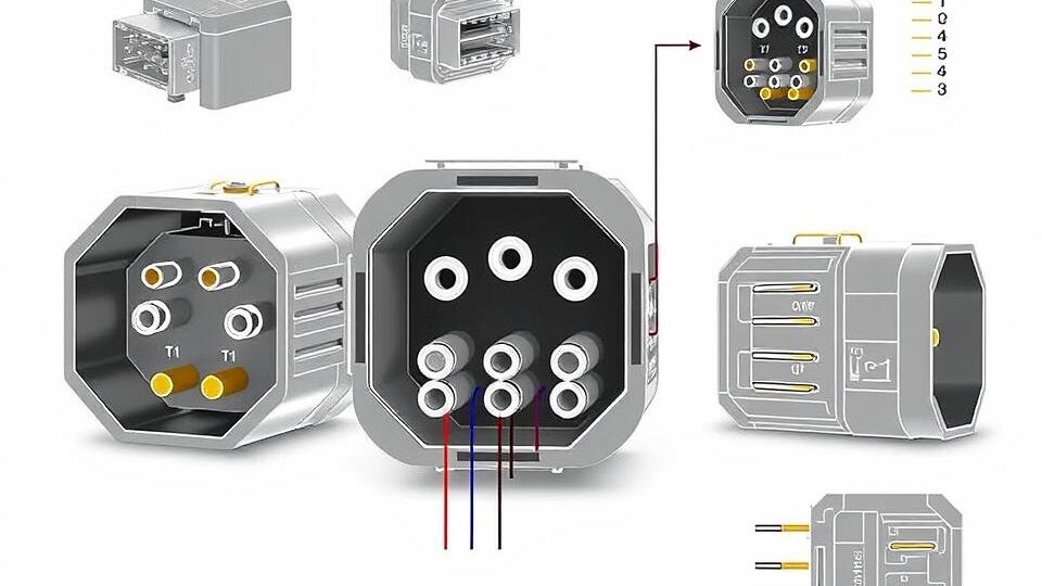
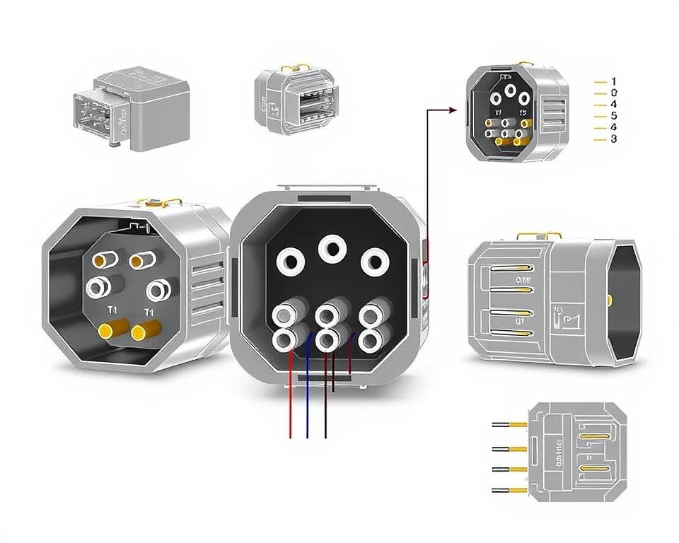
Understanding NEMA Coupler Pinout
Understanding of NEMA connector layout is critical for making proper linkages in electrical systems. Knowledge about distinct pin arrangements ensures security and device operation. There is a range of NEMA interfaces, intended for distinct voltage levels and currents, including:
| NEMA Connector Type | Ampere Rating | Voltage Rating |
|---|---|---|
| L5-15 | 15A | 125V |
| L5-20 | 20A | 125V |
| L14-20 | 20A | 125/250V |
| L1430C | 30A | 125/250V |
| L620C | 20A | 250V |
| L1430C | 30A | 125/250V |
| L630R | 30A | 250V |
Grasping NEMA connector layouts is vital for secure linkages, enhancing effectiveness. It’s critical to align couplers with appliances accurately using twist-lock or straight blade variants, to dodge safety risks.
NEMA Device Wiring
NEMA appliance wiring includes diverse configurations for protected electrical appliance connections. These guidelines ensure that devices work together safely, minimizing risk. Understanding the various NEMA devices and their wiring is vital for specialists.
Various Types of NEMA Devices
NEMA categorizes devices by category based on voltage levels and flow needs. Primary arrangements are:
- 2-Pole, 2-Wire
- 2-Pole, 3-Wire with Grounding
- 3-Pole 3-Wire
- 3-Pole 4-Wire Grounding
- 4-Pole, 4-Wire
- 4-Pole, 5-Wire with Grounding
These setups find use in residences and industrial facilities, operating at 125V, 208V, and 480V.
NEMA Outlet Wiring Explained
NEMA plug wiring changes to accommodate diverse electrical demands, with locking types ensuring consistent interfaces in shaky settings. Such as, the L5-15 plug is rated for 15 amps, frequently used in enterprise settings, whereas the L14-20 is intended for 20 A at 125/250 voltage.
The NEMA labeling convention aids in choosing the appropriate plugs, emphasizing attributes like charge orientation and grounding. Such accuracy secures that devices function safely.
NEMA Outlet Wiring Standards
Accurate wiring of NEMA outlets aligns with electrical standards and security protocols. For instance, L530R receptacles are rated for 30 A at 125 voltage, with L630R models for 250 voltage. Adequate grounding is essential to prevent electrical mishaps.
Selecting approved NEMA plugs and receptacles ensures protected, code-compliant configurations. It’s imperative to check formal protocols when setting up.
NEMA Motor Wiring and Applications
NEMA motor wiring is crucial in electrical engineering, notably for manufacturing use. Understanding how NEMA motor arrangement works guarantees that engines are set up for optimal performance. Motors, like one-phase and three-phase types, require accurate wiring to operate securely and efficiently.
Summary of NEMA Motor Wiring
Comprehending NEMA motor wiring demands knowledge of linkages and configurations. Nearly all three-phase motors are compatible with dual-voltage, meaning they can run on both low (208-230V) and high voltage (460V). High voltage wiring makes a motor use less current than at low voltage. The benefits of high voltage include reduced gauge wiring for the input, a significant benefit for motors over 10 HP.
While both NEMA and IEC units are employed in the market, NEMA models are usually larger and more costly than IEC ones for less than 100 HP deployments. NEMA trips range from size 00 to 9, fit for multiple uses. A typical attribute in NEMA controllers is a Trip Class of 20, designed to trip when a motor’s amperage exceeds 6x the Full Load Amperage in 10 s.
Selecting the Correct NEMA Motor Setup
Selecting the appropriate NEMA motor arrangement impacts overall efficiency and security. A standard three-wire control circuit uses three wires for a power control pushbutton station, allowing simple motor operation. Typical three-phase configurations include the 12 Lead Dual Voltage and 6 Lead, facilitating Wye and Delta arrangements.
IEC motor starters often include phase loss detection, increasing safety. They also feature adjustable Trip Ratings for specific protection in low power operations. Furthermore, many variants have thermal protection, essential for single-phase and Dual Voltage setups.
| Configuration Type | Power Type | Amperage | Typical Use |
|---|---|---|---|
| 12 Lead Dual Voltage | Dual Voltage (208-230V / 460V) | Dependent on motor size | Applications with Wye Start and Delta Run |
| 6 Lead | Single or Dual Voltage | Maximum 32A | Wye/Delta configurations |
| Single Phase | Single-level Voltage | Varies (1-5 amps adjustment) | Applications with Two Speed, Two Winding |
| Delta Connection | Elevated Voltage | Based on configuration | Current Transformers, multiple configurations |
Final Thoughts
Understanding NEMA wiring diagrams and standards is vital for electrical experts looking to enhance their capabilities and comply with electrical security guidelines. These guidelines guarantee safe and high-performing electrical installations but also avert hazards associated with improper wiring. As mentioned, adhering to NEMA criteria results in the augmented performance of diverse NEMA devices and systems.
For technicians, the availability of high-quality resources can greatly affect the outcome of their work. Installation Parts Supply offers a extensive array of wiring products meeting NEMA criteria. This enables specialists to get essential elements for meeting these important standards. Premium supplies and comprehensive expertise of NEMA wiring drawings greatly enhance project safety and efficiency.
In your journey through electrical deployments, always place safety and exactness as a priority. Becoming well-versed in NEMA criteria delivers the understanding required to executing best practices accurately. This ensures that each electrical junction formed aligns with high-quality norms.
Common Questions
What are NEMA wiring diagrams?
NEMA wiring diagrams showcase the arrangements and junctions of NEMA-standard electrical appliances. They follow safety and functional standards set by the National Electrical Manufacturers Association.
What makes NEMA standards important for electrical safety?
NEMA criteria are essential to setting safety and operational benchmarks for electrical equipment. These principles enable electrical professionals minimize electrocution risks, device malfunctions, and fire risk.
Identify the key parts are vital in a NEMA wiring drawing?
Fundamental parts in a NEMA wiring drawing consist of circuit configurations and junction blueprints. These schematics also include comprehensive labels and depict the electrical system’s diverse parts accurately for installations.
What types of NEMA wiring drawings are available?
Various NEMA wiring diagrams cater to various requirements, including power distribution circuits and component interconnection schematics. Every diagram plays a unique role in electrical installations.
What are common symbols used in NEMA wiring drawings?
Common symbols in these diagrams depict switches, fuses, receptacles, and additional components. Utilization of these symbols facilitates unambiguous conveyance and correct understanding of wiring diagrams.
Identify the main features of accurate electrical wiring schematics?
Precision in electrical wiring drawings is characterized by their transparency, comprehensiveness, and explicit annotation. They need to meet NEMA norms to prevent faults in installation.
What is a NEMA connector layout?
A NEMA connector pinout outlines electrical junctions at a connector, displaying particular pin functions. This ensures reliable and efficient connections in electrical systems.
Identify the different kinds of NEMA appliances?
NEMA units consist of various electrical receptacles and interfaces, like adapters and receptacles. They are designed for various current and power specifications to fulfill specific usage needs.
How is NEMA plug wiring set up?
NEMA plug wiring depends on defined amperage and voltage levels needs, following security protocols and electrical codes for various electrical applications.
What guidelines are there for NEMA receptacle wiring?
Standards for wiring NEMA outlets underline complying with electrical codes, ensuring proper polarity, and choosing appropriate wire sizes. This sustains both protection and operation in electrical installations.
What is the method to wire a NEMA motor effectively?
To wire a NEMA motor, one must comprehend its particular one-phase or tri-phase setup. Choosing the right wiring technique is essential, in addition to observing electrical protection for enhanced motor efficiency.
What must be taken into account when selecting a NEMA motor arrangement?
Choosing a NEMA motor configuration requires an evaluation of the project’s power needs and operational characteristics. It’s also crucial to confirm compatibility with current machinery for assured performance and safety.